


")
")
")


-
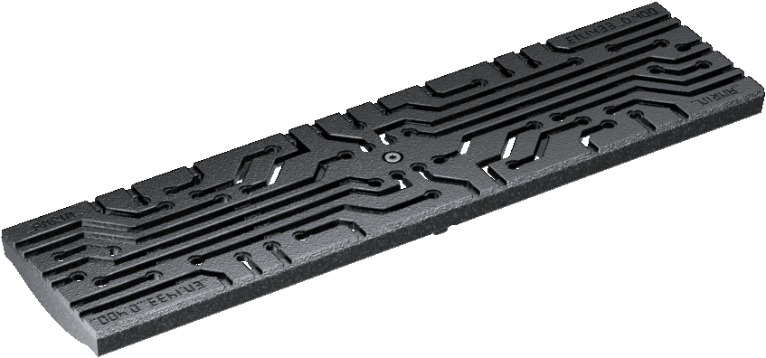
PRODUCT DESCRIPTION
The ANRIN KE-100 edge protection channel is a technically advanced drainage system with a 6 mm thick edge protection profile made of galvanized, KTL-coated steel or stainless steel. Suitable for loads from A15 to E600, which allows it to be used in a variety of traffic areas.
-
PRODUCT INFORMATION
Material polymer concrete Length 50 / 100 cm Width 13.6 cm Height 6.0 cm. 8.0 cm. 10.0 cm / 15.0 - 25.0 cm Weight 9.5 - 25.5 kg Nominal width 100 Edge design Stainless steel Joint formation UNILINK®- Joint
Clasp TwistLock fastening Load capacity A15 (test force 15 kN) to E600 (test force 600 kN) -
SERVICE AND CONTACT
Do you have questions about the product?
Get in touch with us
Tel.: +49 (0) 29 47.97 81-0
Mail: info@anrin.com
Find your local contact person through our ZIP code search
Accessorie for KE-100

Channel body

End cap
closed

Seal set

SELF 100 Smart leaf mesh

Step connector

Sump unit
with dirt trap bucket
DA / OD 110/160 NBR seal rings

Venturi insert
pre-assembled

Stirnwand_KE_100_Rohrstutzen_V
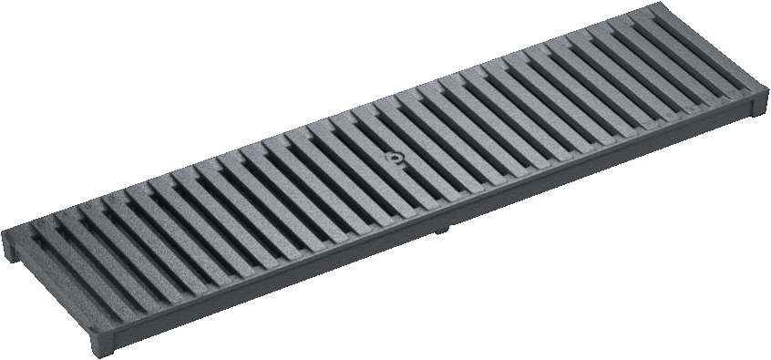
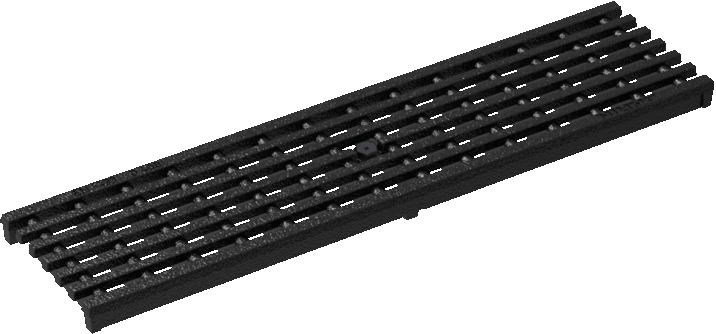
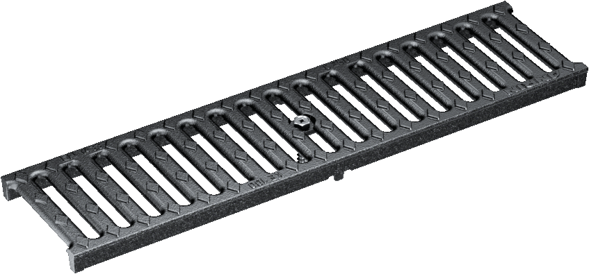
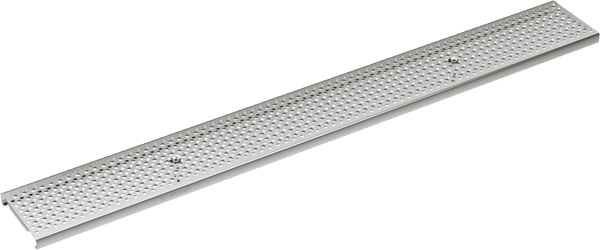
Matching grates
Installation guide
Installation instructions KE-100
ANRIN reinforced channel system made of polymer concrete
ANRIN drainage systems are designed to drain precipitation water safely and quickly. In addition, the structural elements have the task of absorbing static and dynamic loads resulting from traffic-related stresses and discharging them into the surrounding soil.
When selecting, planning and installing ANRIN drainage systems, the following technical regulations must be observed in their currently valid version.
The following installation instructions are schematic representations. They are exemplary and non-binding. The information given here is based on our many years of experience in civil engineering and road construction and on the current state of the art. Irrespective of this, planners and processors are in any case obliged to check the suitability of the products and the installation instructions. The exemplary details are simplified design proposals. Construction superstructures must be redesigned for the specific project.
Important: Insert grates during installation.

1.
Excavate the trench. Place base course and compact. Concrete bed (C 12/15 to class C250 ) on the base course. Add to the base course.

2.
Connect pipe connections to the pipeline.

3.
Place the first channel element and, if necessary, the sump unit on the concrete bed. Align components on string.

4.
Attach end caps.

5.
Complete the string and align components to string.

6.
Pour foundation concrete along the channel flank.

7.
Lay the top layer.

8.
The covering should connect at least 4 mm higher than the cover grate.
Instructions and Regulations
Guidelines and regulations
The current guidelines and regulations of the state-of-the-art technology must be observed for the installation.
For example, these are:
DIN EN 1433 „Drainage channels for vehicular and pedestrian areas“
DIN 19580 „Drainage channels for vehicular and pedestrian areas“
RStO „Guidelines for the standardisation of the superstructure of vehicular areas“
DIN EN 206-1 „Concrete. Specification, performance, production and conformity“
DIN EN 1045-2 „Concrete, reinforced and prestressed concrete structures. Part 2: Concrete – Specification, properties,
production and conformity; Application rules for DIN EN 206-1“
Alternative channels


References


